
It is that time again. Welcome back to Dear ADISRA, where we turn your real-world questions into practical insights for building smarter, more efficient ADISRA SmartView applications.
Every week, we hear from engineers, system integrators, OEMs, and operators who are developing interesting and exciting applications with ADISRA SmartView and need a little assistance to achieve their goals. Because we thought other users might be interested in the same question, we created this series.
In Dear ADISRA, we take your questions, whether they are about architecture, best practices, performance, or new features, and answer them. Hopefully, this is practical guidance from the field.
Dear ADISRA,
How can I connect ADISRA SmartView to my Panasonic FP-X PLC series when it is communicating with a third-party temperature controller?
Answer
The Panasonic FP-X PLC supports several communication protocols, with Modbus RTU being one of the most widely used, especially for integrating with third-party devices such as temperature controllers.
Why Modbus RTU?
Modbus RTU remains one of the most pervasive industrial communication protocols because it is:
– Simple to implement
– Highly reliable
– An open standard (no licensing fees)
It operates on a master-slave or client/server architecture, allowing PLCs to communicate with devices such as sensors, actuators, and temperature controllers over a shared serial network.
Each Modbus message includes:
– Device address
– Function code
– Data (registers)
– CRC checksum for data integrity
Communication typically runs over RS-232, RS-485, or RS-422, making it ideal for industrial environments.
Connecting with ADISRA SmartView
ADISRA SmartView supports both:
– Modbus RTU (serial) – Modbus TCP (Ethernet)
For your third-party temperature controller, Modbus RTU is usually the correct choice.
What You Need to Configure
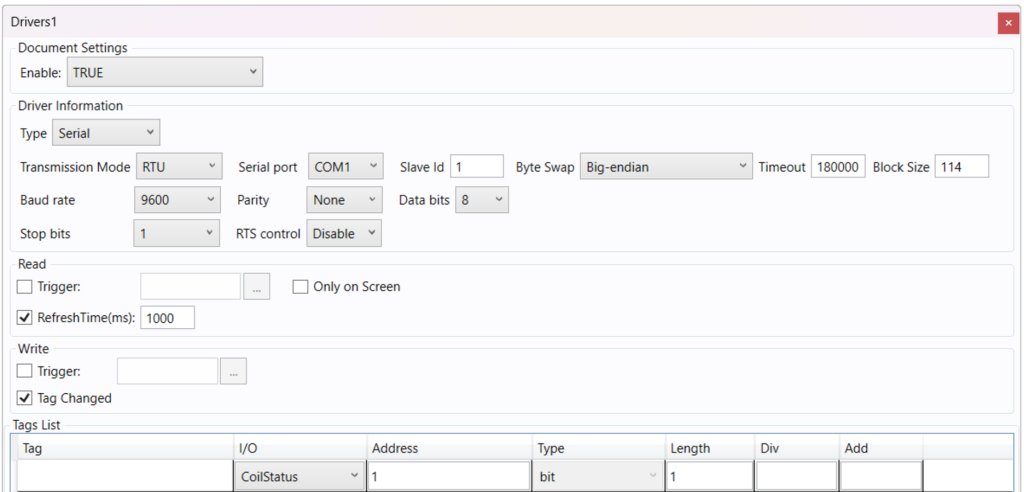
To establish communication, you will configure the Modbus driver in ADISRA SmartView using:
– Connection type
– Serial (COM port for RTU) or Ethernet (IP for TCP)
– Device addressing
– Coils
– Holding Registers
– Input Registers
– Tag definitions
– Data types (Word, DWord, Float, Boolean)
– Register addresses
– Byte order (critical for correct data interpretation)
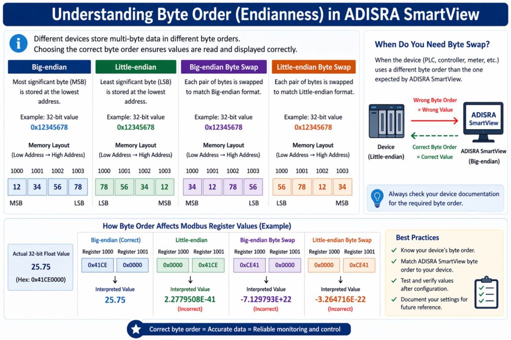
Understanding Byte Order (Endianness)
Because different devices store data differently, ADISRA SmartView allows you to configure byte handling:
– Big-endian (default Modbus): Most significant byte first
– Little-endian: Least significant byte first
– Byte swap options: Used when the PLC and device use different byte orders
Getting this right ensures your temperature values, setpoints, and process data display correctly.
Practical Tip
In most cases, you will need:
– The PLC or device communication settings (baud rate, parity, etc.)
– The Modbus register map from the temperature controller
– The correct byte order configuration
Once configured, ADISRA SmartView can read and write values seamlessly between the PLC and the controller.
Learn More
You can find a complete breakdown of all Modbus driver features directly in the ADISRA SmartView engineering environment help documentation, including advanced configuration options and examples.
Dear ADISRA,
Can you walk through a practical example of a PID control loop in a pasteurization system, including how it handles temperature stability and process disturbances? If possible, is there a working example available in ADISRA SmartView that I can reference?
Answer
A PID controller (Proportional–Integral–Derivative) is a feedback control mechanism used to automatically maintain a process at a desired value, known as the setpoint.
At its core, it continuously calculates:
Error = Setpoint (SV) − Process Variable (PV)
It then adjusts the system using three components:
– Proportional (P): Responds to current error (fast reaction)
– Integral (I): Corrects accumulated past error (eliminates steady offset)
– Derivative (D): Predicts future error (prevents overshoot and oscillation)
PID Control in a Pasteurization System
Pasteurization is a perfect real-world example of PID control in action.
In a typical system:
– Milk must be heated to a precise temperature (e.g., 161°F / 72°C)
– Held for a defined time
– Maintained within strict tolerances
These requirements are not just for efficiency; they are about regulatory compliance and safety:
– Underheating → bacteria survive (unsafe product)
– Overheating → product quality degradation (taste, nutrients)
Systems must meet standards like the FDA Pasteurized Milk Ordinance (PMO).
How the PID Loop Works
– Measurement (PV): A temperature sensor continuously measures the milk temperature.
– Comparison (Error): The controller compares the measured temperature (PV) to the desired setpoint (SV).
– Control Action (MV): The PID controller calculates the manipulated variable (MV), typically by adjusting a steam or hot-water valve.
– Process Response: The system responds, changing the temperature, and the cycle repeats continuously.
Handling Disturbances
Pasteurization systems constantly face disturbances:
– Variations in incoming milk temperature
– Changes in flow rate
– Heat exchanger efficiency (fouling over time)
The PID controller automatically compensates:
– P reacts immediately to temperature drops
– I corrects any lingering deviation
– D prevents overshooting as the system recovers
How ADISRA SmartView Enhances PID Applications
This is where ADISRA SmartView adds real value on top of the control loop:
– Real-time trending: Visualize temperature vs. setpoint
– PID loop visualization: Monitor valve position and system response
– Alarming: Detect deviations, oscillations, or slow response
– Rule-based intelligence: Identify poorly tuned loops and recommend improvements. Detect conditions like heat exchanger fouling for predictive insights
Try It Yourself: PID Demo Application
ADISRA provides a PID Demo Application on our website that you can explore.
In this example, you can:
– Configure multiple cycles (setpoint and pause)
– Adjust Kp, Ki, and Kd values
– Observe how the system responds in real time
The demo simulates a process variable (PV), but the same logic applies to real-world systems like pasteurization.
Here is what is happening behind the scenes:
– The controller compares PV vs. SV
– Calculates the error
– Determines the manipulated variable (MV)
– Adjusts the process to bring PV back to setpoint
This closed-loop behavior is exactly what you would implement in a real pasteurization system.
PID control is the backbone of stable, precise industrial processes, and pasteurization is a perfect example of why it matters.
When combined with the visualization, alarming, and rule-based capabilities of ADISRA SmartView, you move beyond basic control to:
smarter, more predictive, and more reliable operations.
Dear ADISRA,
Can hysteresis be configured at the tag level to apply consistently across all alarm limits? For example, can a user define a single hysteresis value (X) so that Low and Low-Low alarms reset at (limit + X), and High and High-High alarms reset at (limit − X), ensuring a consistent offset across all alarm thresholds?
Answer
What is Hysteresis in Alarm Configuration?
Hysteresis is used to prevent alarms from repeatedly triggering on and off when a value fluctuates around a limit (often referred to as alarm “chatter”).
Instead of resetting exactly at the alarm threshold, hysteresis introduces a buffer:
– High alarms (Hi, HiHi): Activate at the limit but reset only when the value drops below (limit − hysteresis)
– Low alarms (Lo, LoLo): Activate at the limit but reset only when the value rises above (limit + hysteresis)
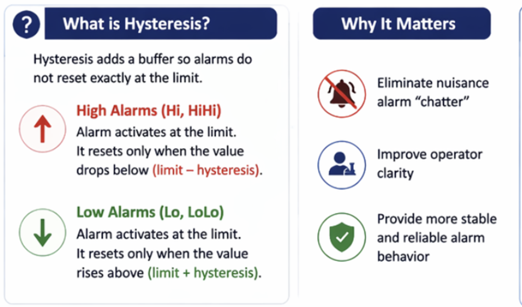
Why It Matters
Hysteresis helps:
– Eliminate nuisance alarm chatter
– Improve operator visibility and confidence
– Ensure more stable and predictable alarm behavior
How to Configure This in ADISRA SmartView
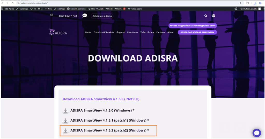
To use this functionality, you will need version 4.1.5.2 or later, available on our website here.
Configuration Steps:
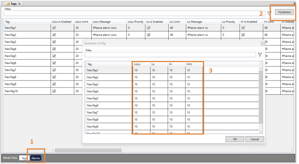
- Open the Alarm Configuration within the Tags document
- Locate the “Hysteresis” button next to the filter – Click the button to open a pop-up window
- Configure the offset values for each alarm type: LoLo Lo Hi HiHi
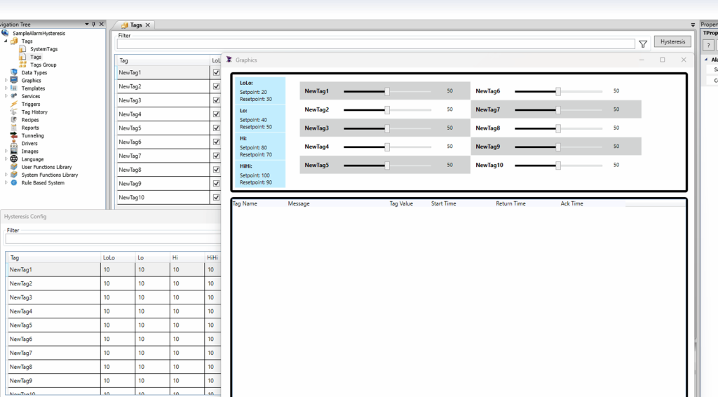
How It Works
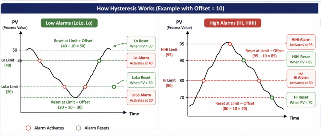
The hysteresis value acts as an offset that adjusts the reset point for each alarm:
– If you configure an offset of 10:
– Low alarms (Lo, LoLo): Reset at (limit + 10)
– High alarms (Hi, HiHi): Reset at (limit − 10)
In the image below, you will see the alarm Lo activating at value 40, but it only resets after reaching >50 due to a 10 offset. Since an offset of 10 is configured for all alarms, the LoLo and Lo will use that offset to set the reset point to LIMIT + 10. and HiHi and Hi will change their reset point to LIMIT – 10.
This allows you to configure different offsets for different alarms and alarm types.
Hysteresis is a simple but powerful way to stabilize your alarm system. With ADISRA SmartView, you can easily configure consistent offsets across alarm thresholds, reducing noise and improving overall system usability.
Dear ADISRA,
What is the best way to configure and organize tags and their associated alarms in ADISRA SmartView to keep my application scalable and easy to maintain as it grows?
Answer
In ADISRA SmartView, tags are the foundation of your application. They represent the data coming from PLCs, calculations, user inputs, and system logic. As your project scales, how you organize those tags and their associated alarms can make the difference between a system that is easy to maintain and one that becomes difficult to manage.
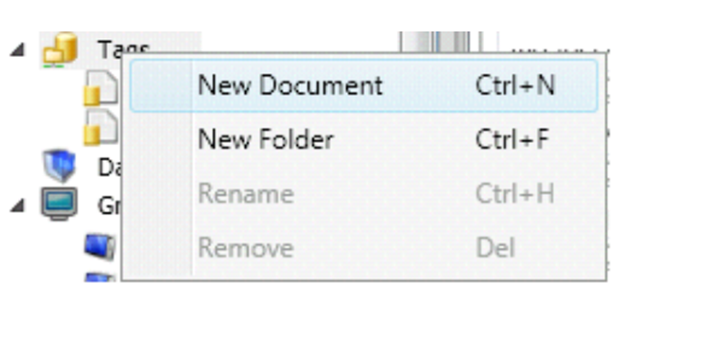
ADISRA SmartView allows you to:
- Create multiple Tag Documents
- Group tags by system, area, or equipment
- Separate concerns such as:
- Process tags (e.g., temperature, pressure)
- Alarm-critical tags
- Calculated or derived values
This approach keeps your project clean and makes it easier to troubleshoot, expand, and maintain over time.
Use Data Types for Reusability
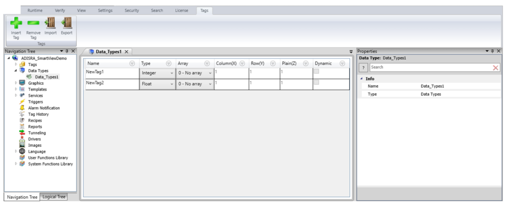
For scalable applications, especially those with recurring equipment (such as tanks, motors, or production lines), you should leverage Data Types.
Instead of creating individual tags for each asset, you can:
– Define a Data Type (e.g., Tank, Motor, Pump)
– Include all relevant parameters (Temperature, Pressure, Level, etc.)
– Instantiate multiple copies as array tags
This dramatically reduces engineering time and ensures consistency across your application.
Configure Alarms at the Tag Level
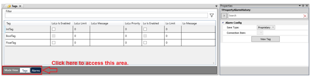
In ADISRA SmartView, alarms are configured directly within the Tags Document, making them tightly integrated with the data they monitor.
Best practices include:
– Enable only the alarms you need (LoLo, Lo, Hi, HiHi)
– Keep alarm limits clearly defined and documented
– Use consistent naming conventions for tags tied to alarms
You can also configure where alarm data is stored (proprietary or database) and even separate storage by Tags Document if needed, providing flexibility for different system requirements.
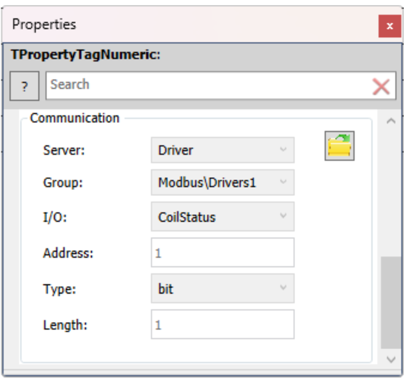
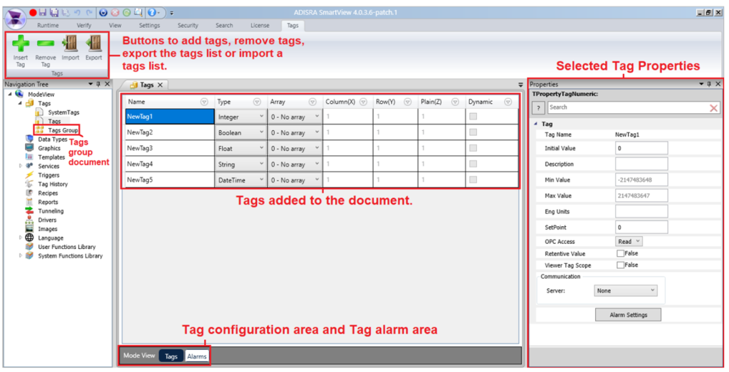
Leverage Tag Properties for Flexibility
Tag properties such as:
– SetPoint
– MinValue / MaxValue
– Description and Engineering Units
– RetentiveValue
can be configured in the Engineering Environment and, in many cases, adjusted at runtime.
This allows you to:
– Adapt alarm limits dynamically
– Support different operating conditions or recipes
– Maintain consistent behavior across system restarts
Using these properties effectively reduces the need for hardcoding values and improves long-term maintainability.
Plan for History and Analysis
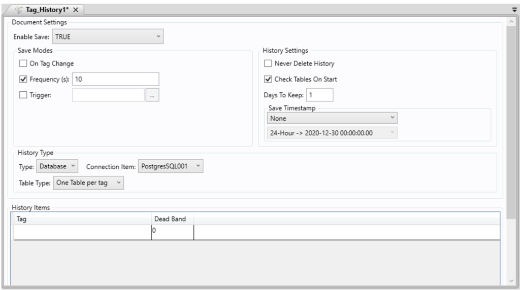
As your system grows, historical data becomes critical.
ADISRA SmartView provides Tag History Documents that allow you to:
– Store data based on:
– Time frequency
– Tag change
– Trigger conditions
– Choose storage methods (file or database)
– Control retention policies
Organizing tags into appropriate history groups ensures you capture the right data without overwhelming storage or impacting performance.
The key to scalability in ADISRA SmartView is structure and consistency:
– Organize tags into logical groups
– Use Data Types for repeatable assets
– Configure alarms directly with the tags they monitor
– Leverage tag properties for flexibility
– Plan for history and data storage
When you follow these principles, your application doesn’t just work; it becomes easier to expand, troubleshoot, and maintain as your system evolves.
Conclusion
At the heart of every successful industrial application is one simple idea: clarity and control.
Whether you are integrating a PLC using Modbus, stabilizing a process with PID control, reducing alarm noise with hysteresis, or structuring tags for long-term scalability, each of these building blocks plays a critical role in creating systems that are not only functional but also reliable, maintainable, and intelligent.
What we have seen throughout this blog is that ADISRA SmartView is designed to bring all of these elements together in a way that is both powerful and practical. From real-time visualization to flexible configuration and rule-based expert system insights, it enables you to move beyond basic monitoring toward smarter industrial operations.
Ready to try ADISRA SmartView? Download ADISRA SmartView here.
Interested in learning more about ADISRA SmartView? Join our next webinar on May 7th, see details below.

Design for Productivity: Advanced Features in ADISRA SmartView
Designing modern HMI/SCADA applications is no longer just about connecting data and building screens; it is about delivering scalable, intelligent systems quickly and efficiently.
In this webinar, we will explore how ADISRA SmartView’s architecture and advanced design features enable developers to improve productivity and build more flexible, powerful applications significantly.
We will begin with a high-level overview of the ADISRA SmartView architecture to help you understand the foundation that supports real-time data processing, modular design, and cross-platform deployment. From there, we’ll dive into the advanced features that allow you to design smarter, not harder.
You will learn how to:
– Reduce engineering time through reusable design strategies
– Build scalable applications using structured data models
– Implement intelligent logic without complex coding
– Make real-time changes without stopping your system
Whether you are a system integrator, OEM, or end user, this session will show you how to move beyond traditional development approaches to build high-performance, maintainable applications with speed and confidence.
ADISRA’s webinar is scheduled for May 7, 2026
Global Time Zones – Start Time:
7:30 AM PDT
9:30 AM CDT (Austin, Texas)
10:30 AM EDT/COT
2:30 PM UTC (Coordinated Universal Time)
4:30 PM CEST
5:30 PM EEST/SAST
9:30 PM WIB
10:30 PM SGT
You can register for the webinar here.
ADISRA®, ADISRA’S logo, InsightView®, and KnowledgeView® are registered trademarks of ADISRA, LLC.
© 2026 ADISRA, LLC. All Rights Reserved.